Fleet & Hangar
Your persistent aircraft, configurations, positions and operational capabilities — ready to support the next flight.
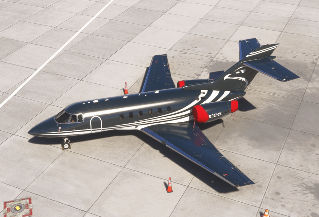
FFX HS125 - 800XP
Every plottable sector recorded for this airframe. Flight Logger records use the actual stored breadcrumb where one exists; historical and other records use the known departure-to-destination sector only.
Manage declared aircraft0 declared · console / CoxBox / manual pilots
Complete route footprint
All history is shown by default. Filter the career, or click a route to inspect one sector closely.
Mapped sectors
| Date | Route | Source | Registration | Distance | Map | |
|---|---|---|---|---|---|---|
| September 18, 2026 | LJPZ → LIRQ | Flight Logger Recorded track | N825HK | 246.1 NM | Open → | |
| September 17, 2026 | LIME → UKLN | Flight Logger Recorded track | N825HK | 732.2 NM | Open → | |
| September 12, 2026 | BKPR → LRTC | Flight Logger Recorded track | N825HK | 413.3 NM | Open → | |
| September 12, 2026 | LGAV → BKPR | Flight Logger Recorded track | N825HK | 334.3 NM | Open → | |
| September 12, 2026 | LGAV → LGAV | Flight Logger Recorded track | N825HK | — | Open → |
FFX HS125 - 800XP
RFoV has recorded 5 sectors in this aircraft across 7 airports. Its story currently continues from LIRQ. Charter work has become a visible part of this aircraft story.
Possible next chapters
RFoV uses this airframe’s recorded history plus the current suitable opportunity set to suggest where its story could go next.
Developer aircraft data
FFX HS125 - 800XP
FlightFX Hawker 800XP Structured Knowledge · Structured · Exact aircraft match
Reference view of the developer-sourced Knowledge Pack. It shows the whole library without contextual filtering. Check marks are local to this browser and do not change the live Flight Companion state.
Preparation · 4
Establish the developer-prescribed safe starting configuration before applying aircraft power.
- Complete the external inspection and remove the aircraft covers and pins required by the simulation.
- Confirm the refuel-panel switches are OFF, the auxiliary hydraulic pump handle is stowed and the landing-gear selector is DOWN.
- Set the parking brake and verify the trims are checked/set.
- Confirm thrust-reverser levers are stowed with reverser power OFF.
- Set both HP cocks closed, both LP cocks up/open, and leave crossfeed/transfer levers in their normal up positions.
The Hawker can be powered initially from the aircraft batteries or a connected GPU; engine starts may then use GPU, APU or battery power.
- For battery-only power: switch BATT ON, leave BATT ISOLATE at NORM and confirm the BUS TIE OPEN annunciation.
- Check each selected battery indicates at least 23 V before continuing.
- For GPU power: connect the GPU in the EFB, switch BATT ON, BATT ISOLATE NORM and EXT PWR ON.
- With either path, verify the engine fire-extinguisher switches are not selected and their indicators are clear.
- Set navigation lights ON; use the logo light when appropriate to visibility.
- Before an APU- or GPU-assisted engine start, set EXT PWR as required and EXT BATT CHG OFF.
Use the simulator/EFB loading tools and performance data with the 800XP limits in mind.
- Keep ramp weight at or below 12,755 kg and takeoff weight at or below 12,701 kg.
- Keep planned landing weight at or below 10,591 kg and zero-fuel weight at or below 8,369 kg.
- The published maximum fuel capacity is 4,536 kg; the optional ventral tank accounts for roughly 680 kg of that capacity.
- Remember MMO is Mach 0.80; with an empty ventral tank, VMO follows the published altitude schedule, while fuel remaining in the ventral tank imposes a 280 KIAS limit.
- Respect flap limits of 220 KIAS at 15°, 175 KIAS at 25° and 165 KIAS at 45°, and the 220 KIAS gear extension/extended limit.
Complete the Pro Line/FMS setup far enough that the aircraft has valid takeoff speeds and N1 reference before the line-up phase.
- Load and verify the flight plan and performance inputs in the FMS.
- Confirm the computed V1, VR, V2 and VF values are complete and transfer the required bugs to the speed tape.
- Enter OAT for takeoff performance and confirm a calculated takeoff N1 value is available.
- Select the FMS-derived N1 reference so the magenta N1 bugs are displayed on the engine presentation.
Startup · 5
Use the APU as the pneumatic/electrical source when that is your selected start method.
- Open the left LP cock and switch the APU master ON without starting yet.
- Select the left fuel pump to EMERG and confirm the associated low-pressure indication clears.
- On the APU panel set OVV NORM, TEST NORM, generator CLOSE and bleed air OFF; leave the fire-extinguishing control guarded.
- Press the APU fire test/control as described by FlightFX and verify the expected fire, low-oil-pressure and generator indications before start.
- Momentarily select APU MASTER to START, then monitor the start until RPM reaches 100%, EGT is within limits and READY TO LOAD is illuminated.
- After about two minutes of stable APU operation, select APU BLEED AIR ON and verify the bleed-air indications are normal.
Use this path only when neither GPU nor APU is available and you need No. 2 engine to provide aircraft power.
- Set EXT PWR OFF, test ENG FIRE 1 and 2, switch the beacon ON and right fuel pump ON.
- Set ENG CMPTR 2 to AUTO, close MAIN AIR VLV 2 and switch START PWR ON.
- Select ENG 2 to OPERATING.
- At approximately 15% N2, move the right HP cock up/open.
- After the engine is running, switch START PWR OFF and continue with the remaining before-start checks.
Once a stable electrical source exists, configure the cockpit systems before the normal two-engine start.
- Close the bus tie when external power is not supplying the aircraft, and switch the inverters ON and check them.
- Power the radio masters and check transponder/TCAS configuration.
- Turn passenger and crew oxygen supply ON and verify the relevant side panels.
- Set CABIN HIGH DATUM as required for very high departure fields, leave EGPWS switches deselected and complete the MWS test.
- Verify both AHRS selectors are NORM, transfer lights are out, the AUX HYD handle is fully in and the dump valve is shut.
- Set pressurisation to AUTO with the manual cabin-altitude control fully decreased; preset cabin altitude using the FlightFX departure/cruise rule.
- Complete overhead tests, AP/YD check, electric-trim test, FMS/navaid/V-bug setup, N1 reference and altimeter/ESIS checks.
- Set cabin signs ON and emergency lights ARMED.
Use the FlightFX normal start sequence with the engine computers in AUTO.
- Set the brakes PARK, beacon ON, both ENG CMPTR switches AUTO and the required fuel pumps ON.
- Select START PWR ON and verify its indication.
- Confirm both LP cocks are up/open and guarded.
- Start No. 2 engine first if it is not already running; when N2 reaches about 15%, raise/open the right HP cock.
- Start No. 1 engine; when N2 reaches about 15%, raise/open the left HP cock.
- Monitor both starts for stable acceleration and normal indications.
Transition from start configuration to the normal ground-running configuration.
- Switch START PWR OFF and disconnect/switch OFF external power if it was used.
- Confirm generators 1 and 2 are online and check aircraft volts and amps.
- If the APU remains running, trip its generator so READY TO LOAD is shown; use APU bleed/air-conditioning as required.
- Switch both alternators ON.
- Switch windshield and pitot/vane heat ON and check pitot current.
- Set engine anti-ice as required and verify the airbrakes are SHUT.
Taxi / Run-up · 5
Complete the FlightFX APR functional test before takeoff.
- Arm APR and verify the white armed indication.
- Slowly advance the right thrust lever until No. 2 N2 is roughly 5 percentage points above No. 1.
- Confirm APR override activates with the expected green indications.
- Return the right thrust lever to idle.
- Disarm APR and verify the APR override/armed indications clear.
Check both engine computers before takeoff, then return them to AUTO.
- Select both ENG CMPTR switches to the overspeed-protection/manual test position and verify both computer annunciations illuminate.
- Advance the thrust levers slowly and confirm each engine remains controllable without runaway behaviour.
- Return both thrust levers to idle.
- Return both ENG CMPTR switches to AUTO and confirm their annunciations extinguish.
Verify that the rudder-bias system responds correctly before departure.
- With both rudder-bias switches OFF, confirm the rudder-bias annunciation is present.
- Advance one thrust lever to the test power and verify there is no bias input with both channels OFF.
- Select channel A ON and verify the expected rudder-pedal bias; switch it OFF and confirm the input is removed.
- Repeat with channel B, then with both channels ON to confirm the increased combined bias.
- Return the thrust lever to idle and repeat the developer test for the opposite engine.
- Finish with both rudder-bias switches ON and the annunciation extinguished.
Verify the reverser system and its interaction with rudder bias while still on the ground.
- Arm thrust-reverser power from the forward-panel switchlights.
- With both rudder-bias channels ON, advance the test engine to the developer test power and observe the expected rudder bias.
- Deploy the opposite engine reverser and verify the rudder-bias input is removed while the reverser transition/deployed indications behave normally.
- Return the reverser to idle/stowed and confirm the indications clear.
- Return the thrust lever to idle and repeat the same functional check on the other side.
FlightFX permits idle reverse to manage taxi speed but prohibits powered reverse during taxi.
- Use normal braking/taxi thrust as the primary speed-control method.
- Idle reverse may be used to reduce brake wear when appropriate.
- Do not apply powered reverse thrust while taxiing.
Takeoff · 2
Configure the aircraft for departure before entering the runway.
- Check brakes, flight instruments and altimeters; the two altimeters should agree within 40 ft.
- Confirm thrust reversers remain armed and set the planned takeoff flap position.
- Secure seats/harnesses and close the flight-deck windows.
- Check battery current is below 20 A, fuel quantity/balance and the FMS setup.
- Set TCAS to TA/RA and confirm the flight controls are full and free.
- If using the APU for takeoff air-conditioning/pressurisation support, leave it running for this phase.
Complete the final runway-entry items immediately before applying takeoff thrust.
- Set exterior lights and transponder as required.
- Configure engine anti-ice and ignition for the actual simulator conditions.
- Check the warning system has no unresolved takeoff warning.
- Confirm FATS: flap setting, airbrakes, trims and takeoff V-speeds.
- Close MAIN AIR VALVES 1 and 2, set pressurisation AUTO and close the flight-deck heat valve.
- Set takeoff thrust and arm APR.
Climb · 2
Transition from takeoff configuration once airborne and safely climbing.
- Retract the landing gear.
- Open both main air valves after takeoff.
- If the APU was used for takeoff, switch APU bleed OFF and shut the APU down when appropriate.
- Engage the yaw damper and retract flaps on schedule.
- Set climb thrust, disarm APR and select engine synchronisation to N1 or N2 as appropriate.
- Set anti-ice and ignition as required and verify no duct-overheat warning is present.
FlightFX lists a recommended turbulent-air target for the Hawker.
- In turbulent conditions, use 230 KIAS / Mach 0.70 as the developer-recommended reference unless another procedure or restriction requires less.
Cruise · 2
Cruise is primarily a systems-monitoring phase in the FlightFX normal flow.
- Check cabin pressurisation and oxygen quantity/status.
- Continue to configure engine anti-ice and ignition for conditions.
- Monitor the aircraft systems and engine indications throughout cruise.
- For normal cruise operation, keep engine ITT at or below the FlightFX 932°C cruise reference rather than using maximum-continuous abnormal power as a routine setting.
The ventral tank has its own transfer procedure and imposes a lower speed limit until emptied.
- When wing-tank quantity reaches about 1,497 kg, open the auxiliary/ventral transfer lever.
- Monitor the ventral-tank indication and the transfer annunciations while fuel moves to the wings.
- Observe the 280 KIAS limit while fuel remains in the ventral tank.
- After transitioning from climb to cruise, leave the transfer open for roughly five minutes even if the indication already reads empty.
- Close the transfer lever once transfer is complete, confirm the transfer annunciations extinguish and verify the 280 KIAS speed restriction is no longer displayed.
- Plan to have the ventral tank empty before a normal landing.
Descent · 1
Prepare the pressurisation system and crew for arrival before the high-workload approach phase.
- Confirm both main air valves are OPEN during descent.
- Set the pressurisation controller for the destination using the destination QNH and the FlightFX elevation correction method.
- Complete the descent/arrival briefing.
- At low thrust during descent, do not treat an erratic or zero fuel-flow indication by itself as unexpected; FlightFX documents this as normal simulator behaviour.
Approach · 1
Establish the arrival configuration before the final landing checklist.
- Set and cross-check the altimeters.
- Close the flight-deck heat valve and set exterior lights as required.
- Turn cabin signs ON and confirm seats/harnesses are secure.
- Ensure the nosewheel-steering handwheel is clear.
- Check fuel quantity and balance.
- Set/verify VREF, VAPP and landing distance; the FMS normally sets VAPP to VREF +10 KIAS unless you deliberately choose another value.
- FlightFX notes that real-world operators may start the APU around this point; use it as your simulator operating preference rather than an RFoV requirement.
Landing · 4
Complete the final landing configuration before touchdown.
- Confirm airbrakes are SHUT and arm APR.
- Lower the landing gear and verify the nosewheel-steering handwheel is centred.
- Switch engine synchronisation OFF and re-check altimeters.
- Set the landing flap; use 45° when lift-dump operation is planned.
- Close both main air valves for landing.
- Disengage autopilot and yaw damper before landing as required by the FlightFX procedure.
FlightFX publishes an explicit landing-speed and distance correction when icing conditions exist or ice remains on unprotected parts of the airframe.
- Add 10 KIAS to the normal approach and landing speeds.
- Increase planned landing distance by 15%.
Lift dump is a ground-only system and requires weight-on-wheels plus the landing flap configuration.
- Before touchdown, ensure flaps are at 45° if lift dump will be used.
- After weight-on-wheels is detected, move the airbrake control fully to DUMP.
- Confirm the command drives the flaps to 75° and opens the wing spoilers/airbrakes for lift dump.
- Never use lift dump in flight.
Keep the go-around sequence available from the landing phase so it remains reachable when a landing is discontinued.
- Apply thrust as required.
- Retract flaps initially to 15° and establish approximately 12° pitch.
- Maintain at least the FlightFX published go-around speed reference while cleaning up.
- Retract the landing gear once a positive climb is established and continue the normal climb cleanup.
After Landing · 1
Return the aircraft to a safe taxi configuration after landing.
- Return airbrakes/lift dump to SHUT and retract the flaps.
- Set exterior lights as required.
- Switch pitot/vane heat OFF; leave anti-ice configured as conditions require.
- Disarm APR, set the transponder to standby and switch weather radar OFF.
- Use the APU and air-conditioning as required for the taxi-in and shutdown plan.
Parking · 1
Establish the initial shutdown configuration at the stand.
- Set the parking brake.
- Switch thrust-reverser power OFF.
- Switch emergency lights OFF.
- If the APU will carry the aircraft during shutdown, confirm it is stable and available before closing the engine HP cocks.
Shutdown · 2
Use this branch when the APU is already running and will support the aircraft while both engines are stopped.
- Close both engine HP cocks, switch the fuel pumps OFF and switch both ENG CMPTRs OFF.
- Switch the beacon and cabin notices OFF and verify generator-fail indications after engine shutdown.
- Switch screen heat and alternators OFF.
- Power down both radio masters and disarm the ESIS.
- Shut the APU down when no longer required, then move both LP cocks down/closed.
- Switch exterior/interior lights and oxygen supply OFF, then switch BATT OFF.
- Switch vestibule/cabin lights OFF as the final cabin power item.
Use the developer branch that keeps No. 2 engine running long enough to support the remaining powered checks.
- Set parking brake, thrust-reverser power OFF and emergency lights OFF.
- Close MAIN AIR VLV 1, close the No. 1 HP cock, then switch the left fuel pump and ENG CMPTR 1 OFF.
- After No. 1 engine stops, verify its generator-fail indication and switch cabin notices, screen heat and alternators OFF.
- With No. 2 still running, switch both radio masters OFF and disarm ESIS.
- Close MAIN AIR VLV 2 and switch the standby inverter OFF.
- Close the No. 2 HP cock, then switch the right fuel pump and ENG CMPTR 2 OFF.
- Verify the No. 2 generator-fail indication, then switch beacon OFF and move both LP cocks down/closed.
- Switch remaining exterior/interior lights and oxygen supply OFF, then switch BATT OFF and extinguish the vestibule/cabin lights.